BV523 Starting
Resources
- BV_COM2 User guide and software.
- BV-COM2 Software only
- Page Link See the links section at the bottom of the page for link to the FTDI website
- Pictures BMP A few pictures in BMP format
The BV523 comes with or without a colour display, without the colour display the connector can be used for extra I/O. For the information about the I/O see the data sheet. The device has a built in USB interface that uses the FTDI virtual COM port. This chip is chosen because of its widespread use. It is built into Linux and has drivers for most of the popular operating systems.
RTC
The BV523 is equipped with a battery backed RTC, at first switch on the RTC will report as if it is not there, the time and date needs to be set before it can be recognised. The supplied battery goes in the holder + side up and must be pushed all the way home. Once this is done, the date and time will be maintained even when there is no power to the device.
If the battery is not fitted correctly the clock can still maintain the time but appears as though its has stopped. If this is the case make sure that the battery is in correctly or clean the contacts
COM Port Driver
Note the following instructions apply to the Windows Operating System and not the BV514
Obtain the driver from the FTDI website (link above). It is the VCP driver that is required, download the one for your operating system. When the BV523 is first plugged into the USB if the driver is not installed then go through the standard procedure of installing the driver. There are full instructions on the FTDI web site. The driver will create a COM port and it is important to know which COM port has been created, particularly if there are lots of COM ports on your system.
To determine the COM port in Windows XP, go to the control panel and then System. At the System dialog choose the hardware tab then the device manager button. All of the COM ports will be listed under the +Ports[COM & LPT] tree. Look for the "USB Serial Port[COM<n>]". This is the USB COM port the <n> will be the port number.
Terminal Emulator
The device works through a COM port and terminal emulator (BV_COM2) above.
- Start the program by double clicking the exe file. (file can be downloaded from above)
- Select the com port for your system
- Select a baud rate of 115200
- Press the connect icon
 and it will turn green
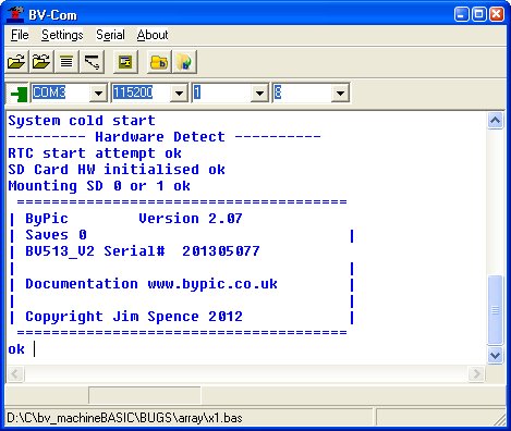
The screen should look something like the above, if not press the reset ![]() icon.
icon.
The reset is connected to DTR and is a standard used throughout the BV5xx range. If using a BV513-M with something other than the BV101/3 then the DTR from the serial device must be connected for the reset to work.
Simple Interactive Basic
BV-Basic is interpreted and thus always available so try:
print "fred"
a#=12.4
print a#
b#=12.4*77.25
print b#
Programs
A program consists of a collection of functions, cumulating in a final function which is the application. The functions can be stored in RAM or Flash. In this way a virtual language can be created to suit a particular application. Functions can be written using a text or program editor and then downloaded to the BV513 using 'tload'.
A recommended program editor is PS_PAD which has most of the BV-Basic keywords although the ini file does need updating.
Using Tload
Text load is the way to get programs from the program editor into the devices RAM. As an example this function:
function hello()
dim j
   for j = 1 to 5
      print "j="j,"hello world"
   next
endf
Create a file called hello.bas, save it and using the text load icon get the dialog box, browse for the file:

Before pressing send type 'tload <enter>' into the terminal screen so that the device knows to expect a tloaded file.

The result should be something like above. A refinement on this process is to use the send text facility which will save having to type tload each time. Some thought though needs to be put into this. It would be advantageous to clear all previous functions before loading and so 'cold' will be needed. The whole command would be.
cold
tload  -- wait for device to send 'Send text file.."
This can be implemented with cold \n\w200 tload \n\w300. The wait (\w<time>) is important to give the device time to respond before sending any information. The \n are the same as pressing (CR).

Make sure the 'Send first' check box is checked. There is no need to enter any text now, simply press send. Press CR when entering the send text and it will be saved in the drop down box for next time.
SD Card
The SD card is used for holding programs, data, fonts and pictures. The latter two if the screen is fitted. The normal method of getting data onto the card is either directly using the PC or via the device using fbload. The fbload method means that you do not have to remove the card from the device. The syntax for this is:
fbload("filename")
NOTE for this to work properly hardware handshaking must be enabled.
Rookie
This is a collection of functions that can be downloaded and saved to Flash to make programs much easier to write for the sacrifice of a little efficiency but any optimisation can be carried out at a later stage only if necessary.
Rookie is installed using the same technique as above. There is a different rookie for each type of development board, full instructions for installing and the firmware itself is here on the ByPic site.
Examples, Setting the alarm to turn the BV523 back on
For this to work the battery in the RTC must be installed, assume the time is 14:33 and the date is 12 of March 2013
- Make sure the time and date are set:
setdate(13,3,12,2) // year,month,day of month,day of week
settime(14,33,0) // hours, minutes, seconds
- Set alarm for 14,35
rtc_setAlarm(12,3,14,40,0) // set alarm to come on on 12 March 14:40
poff() // at this point the BV523 will shut down and then come back on at 14:40
Using the Screen
When the screen is fitted it will start up with a sign on message, to get normal information to the screen use the print command in the form:
ditext("fred")
All sceen commands start with di (DIsplay) Some other useful commands are:
- dicls(<colour>) - clears the screen to the given colour
- dihome() - moves cursor to home position but does not clear the screen
- diback(<colour>) - sets the background colour
- difor(<colour>) - sets the foreground colour
A complete listing of the commands can be found on the ByPic site in the documentation section.
Images
To display an image on the device it needs to be in the correct format and should start out as a BMP file with a 24 bit colour depth, it also should NOT exceed the screen resolution which is 240 x 320. Images can only be loaded in portrait mode, if a landscape image is required then rotate the image by 90 degrees first using a paint program.
A BMP file will not directly load into the device it needs to be converted to a BMC file first this can be done in two ways:
- Use the built in converter of the binary load
- Use the BMPConverter program and download the BMC file directly.
To give an example use the tiger.bmp image in the zip file above.
Method 1
Convert tiger.bmp to tiger.bmc by using the BMP Converter program. Put the file onto an SD Card, put the SD Card into the BV523 and then type diimage("tiger.mbc",0,0) and the image will be loaded. The 0,0 will specify the x and y co-ordinates to load the image to.
Method 2
There is a slight complication because it loads the image from COM2 but the loading process is slightly slower then the Baud rate and so there needs to be a hardware handshake set up to control the download. This is simple enough to do:
1: Make sure you have loaded 'rookie'
2: Type rts_on(). If you get an error then you have not loaded rookie
3: In the Serial drop down menu of BV_COM check CTS
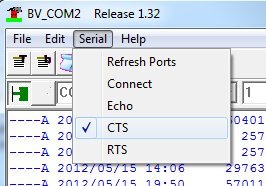
Hardware handshaking is now enabled, it is disabled by default.
We can now download an image via com2 (UART2), we don't need to convert to BMC first as there is a converter built into BV_COMM This ![]() icon will bring up the binary load transfer dialog.
icon will bring up the binary load transfer dialog.
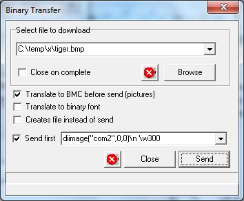
Provided that the image is in the dialog box this will work without typing anything in to the terminal as all of the appropriate commands are send first. Also the file is converted from BMP to BMC on the fly because the 'Translate..' checkbox is ticked.
Fonts
The BV523 has just one built in font, user fonts can easily be created with the help of CBFG, there is a link to this software here under 'Free Software' look for CBFG. Fonts are stored on the SD card and so there can be a virtual limitless supply. The font command has three syntax's:
difont("0") // note this is a zero with double quotes
difont("filename")
The first syntax will select the default font and the second will choose a font on the SD Card. The following will give an example of how to create and use a font.
1: Start CBFG
Select the LED font as shown
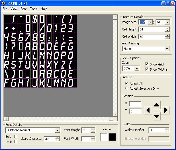
This is quite a large font that looks a bit like an LED segmented display, make sure all of the boxes match to get the same results as me. Note with the settings as shown not all characters are available, as I only need numbers this is okay, however if you need the full set then increase the image size, use the smallest image size possible in order to keep the file size down.
2: Convert and download the font to an SD Card
Use the tool built into BV_Com to create a .bf file by checking the "Create file instead of send" dialog box. Transfer this to the SD Card and then type difont("fontname"). Using ditext("text") will now use that font.
Touch Screen
The screen has fitted a resistive touch panel that can be accessed via ByPic, however it does need calibrating before use and the calibration values are stored in block 0 of the AT Flash. If this becomes erased then the program will request a calibration before continuing.
There is a simple paint program that demonstrates the touch screen, see the ByPic website in the projects section.
Power Control
The BV523 has a unique power control that uses the alarm from the Real Time Clock (RTC). This mechanism enables complete power shut off and therefore zero power consumption until the RTC alarm goes off. There is already an example of this in the text.