BV508
 This is a small self contained microcontroller board with an on board operating system; ByPic that can be programmed using the serial interface and just a simple text file.
The pins are on a 0.1” (2.45mm) pitch and so can be plugged into a breadboard or a standard strip board.
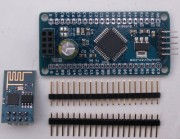
The board comes with a socket for connecting to an ESP8266 Wi-Fi module and with firmware for driving that module making it easy to build server or client applications.
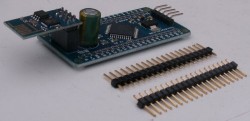
**NOTE: It comes with the pins but not attached so that the user can use it either way round.
Size: 30mm x 60mm
There are TWO microcontrollers on this board, a PIC32MX179 with 256K Flash and 64k RAM running at 40MHz and an ESP8266 wi-fi controller. This is on a separate board with its own antenna
There is a socket for the ESP8266 that connects to UART1. In addition the power regulator can handle the current required for the ESP8266.
Qiuck Start
- Down load BVSerial (the IDE) as described here.
- Connect the BV508 to a USB to serial device and establish communication. Further details are here if this proves difficult. Serial connection details are in the text below.
This next bit is if there is an ESP8266 device plugged in with up to date ByPic firmware (vF1_1.9.17 or later)
http://www.byvac.com/downloads/BV508/u3.bas
- Copy th above link by selecting and then CTRL+C
- In the IDE select scripts>Open URL in clip and this will open the above URL
- Press F4 to load it into the BV508
- type test()
Hardware
The board is based on a PIC32MX170F256D that has 256k Flash, 64k RAM and operates at 40MHz.
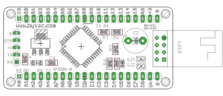
Connectors
NOTE: This chip has a Peripheral Pin Select (PPS) device and so most of the pins used below could be changed. The pin functions described in the tables below are those used by the ByPic firmware or rookie which is added to the firmware.
Serial
| Pin Name | Function |
|---|---|
| G | Ground |
| DTR | Connected to the reset, a pulse on this pin will reset the PIC |
| +V | Main power input Maximum input voltage is 18V |
| TX | Output from PIC UART 2 (RB10) |
| RX | Input to PIC UART2 (RB11) |
The on board regulator can handle up to 1A although with the PCB heat sink it will be lower than this. The ESP8266 consumes an average of about 100mA peaking to 200 to 200mA so it is well withing the regulators range. The minimum voltage should be 4.5V as this will allow sufficient voltage drop to give 3.3V
The default Baud rate is 115200 with 8 data bits and no parity. The UART pins used are 5V tolerant so it can be used with either a 5V or 3.3V USB to Serial device.
ESP8266
| Pin Name | Function |
|---|---|
| TX | Output, connected to PIC UART1 RX (RA0) ** |
| GND | Ground |
| CH_PD | Power down pin, high for power up connected to PIC RA1 |
| GPIO2 | Connected to solder pad and then to RA7 |
| RST | Reset connected to RA3 |
| GPIO1 | Connected to solder pad and then to RA2 |
| VCC | 3.3V from regulator |
| RX | Input, connected to PIC UART1 TX (RA4) ** |
** Version a PCB has a solder jumper to either UART1 or UART2, RA0 and RA4 is UART1 which is the default (see below).
By default GPIO1 and 2 just go to the solder pads that are left unconnected. If this pins are required the solder pads can be shorted to connect the the PIC pins as in the above table. The pins used are marked on the PCB.
GPIO
All of the GPIO pins are brought out to the side connectors, these are laid out at 0.1" grid and so will mate to any standard breadboard etc. The pins are marked on the PCB and so the table will show only those pins that are not obvious.
| Pin Name | Function |
|---|---|
| V+ | This is the input voltage and is connected directly to the input side og the regulator |
| RS | Connected directly to the MCLR pin of the PIC |
| +3 | Output of the 3.3V regulator can be used for powering external equipment |
| G | Ground |
Some pins are duplicated, for example RB10 (UART2 TX) and RB11 (UART2 RX) appear on the side connector and also on the serial connector so take care when deciding which pin to use. As a reminder the pins used for these and other functions are marked on the PCB.
I2C Interface
The I2C interface can either be a slave or master. It has built in 4.7k pull up resistors and is wholly controlled by software. A library is available for either master or slave. To use this interface the software needs to be installed first via the serial interface.
SCL: B8
SDA: B9
Power
A feature of this device is that the 3.3V regulated power also has a 1000uF capacitor to act as a 'reservoir'. This is because the ESP8266 can peek largish currents and it has been found that such a capacitor is in fact needed.
JRX, JTX Jumpers.
See history added for version PCB-a

The ESP8266 can be set to one of either of the two UART's on the PIC32. There are solder jumpers and by default both TX and RX are set to UART1. This way there is not interference with the normal operation of the device.
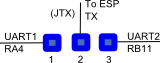
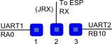
If the jumpers are set the other way then the device can be programmed and controlled via the ESP8266. To do this successfully requires that the ESP8266 be programmed with the transparent bridge firmware that can be found here.
PIC32
The processor is a PIC32MX170, this has 256K flash and 64K ram. A proportion of the flash is taken with the ByPic operating system. However there is still sufficient room for complex programs. The actual spare flash is approximately 133k which is good enough for several thousand lines of code.
Some other features of this processor are:
- 40MHz clock rate
- 20uA low current mode (may not be achievable on this device)
- Audio features
- ADC 10 bit
- Charge Time Measurement Unit
- Comparators
- Timers (5)
- SPI, I2C, UART x 2
- Some pins are 5V tolerant
Circuit Diagram

Click image to enlarge
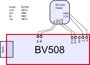
SD Card
To use an SD card with this device do the following.
1) Replace the normal firmware with the SD Card firmware here
2) Wire up an SD card using a suitable holder using the following wiring
| PORT | Description | SD Card |
| RB15 | Clock | CLK |
| RB6 | MISO | DO |
| RB5 | MOSI | DI |
| RB14 | CS | CS |
** Don't forget the SD Card requires 3.3V
3) You should now see that the firmware will show a 0:/ ok prompt, this means that the SD is in place. NOTE the prompt will only show if there is an actual formatted SD card in place.
4) Optional: unzip the sd_card rookie and put that on the SD card, do a reset and it will load rookie3 in about 5 seconds. Also observe how main is used to load the rookie firmware.
Programming
The device has installed ByPic. This is permanently in flash and makes programming much easier. No programmer is required simply download the code using a serial connection, the code is written in text, this includes the libraries and so can be modified by the user as required.
To get started connecting the device to a serial port and using the ByPic language follow this link.
Programming with a PICKit
The device can be programmed in C using a PICKit but be warned that the boot loader will be overwritten and you will not be able to use ByPic anymore via the boot loader.

History
November 2014 PCB Version - 0
September 2015 PCB Version a - added TX and RX jumpers