BV502 (There is a version 2 here)
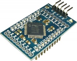 The BV502 (Mini-Max) PIC32
This is a small self contained microcontroller board with an on board operating system; ByPic that can be programmed using the serial interface and just a simple text file.
The pins are on a 0.1” (2.45mm) pitch and so can be plugged into a breadboard or a standard strip board. The module is intended to be plugged into a larger system or used multiple times to provide a distributed network, one for each joint on a robot for example.
**NOTE: It comes with the pins but not attached so that the user can use it either way round.
Size: 25mm x 45mm

Comparison with Adruino
Hardware
The board is based on a PIC32MX150F128D that has 128k Flash, 32k RAM and operates at 40MHz.
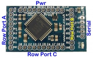
It has an on board regulator and so can be powered from 5V (up to 6V). All of the pins have been brought to the edges of the board in port order for convenience. The PCB markings reflect the port name and so C0 is for example port c pin 0.
Serial Interface
This is connected to UART2 (115200 Baud, 8 data bits, 1 or 2 stop bits) and is the main form of communication with the board. There is also a UART1 that can be used for any other general communication, this is accessed via the pins round the board. The MX1 has a pin select facility and so this can be directed to several alternative pins.
As an example UART1 could be any of the following:
TX RX
A0 A2*
B3 B6
B4* A4
B15 B13
B7 B2
C7 C6
C0 C1
C5 C3
* These pins are used in the standard ‘rookie’ software.
The UART2 interface is at the front of the board, using a USB to serial this can also supply power and reset via DTR. Programming is done via the UART 2 interface by sending text to the device. This can be saved to the processors flash to become a stand alone application.
RX: Is an input and will receive signals from a USB to serial converter or similar. It must NOT be connected to a COM port directly (i.e. the 9 pin type)
TX: Is the output
I2C Interface
The I2C interface can either be a slave or master. It has built in 10k pull up resistors and is wholly controlled by software. A library is available for either master or slave. To use this interface the software needs to be installed first via the serial interface.
SCL: B8
SDA: B9
Power
Power is supplied to the board from either the serial, I2C or GPIO connectors. The board works at 3.3V and this is provided by the on board regulator. The maximum voltage the regulator can handle is 6V and so can be supplied via 4x1.5V cells for battery operation.
PIC32
The processor is a PIC32MX150F128D, this has 128K flash and 32K ram. A proportion of the flash is taken with the ByPic operating system. However there is still sufficient room for complex programs. The actual spare flash is approximately 33k which is good enough for several thousand lines of code.
Some other features of this processor are:
- 40MHz clock rate
- 20uA low current mode (may not be achievable on this device)
- Audio features
- ADC 10 bit
- Charge Time Measurement Unit
- Comparators
- Timers (5)
- SPI, I2C, UART x 2
- Some pins are 5V tolerant
Circuit Diagram
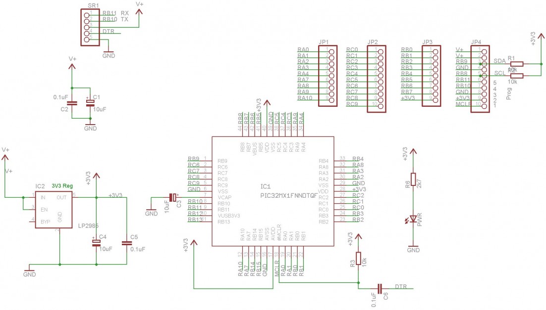
Click image to enlarge.
Programming
The device has installed ByPic. This is permanently in flash and makes programming much easier. No programmer is required simply download the code using a serial connection, the code is written in text, this includes the libraries and so can be modified by the user as required.
To get started connecting the device to a serial port and using the ByPic language follow this link.