BP1 Construction
The BP1 is normally supplied in kit from and so some knowledge of soldering is required.
The ByPic is a PCB based on the Arduino Uno design with exactly the same physical dimensions. This is the construction guide and physical details. For the software refer to www.bypic.co.uk.
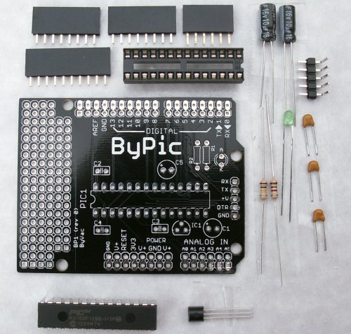
Parts List
- R1 1k
- R2 100k
- C1,C5 10uF
- C2,C3,C4 0.1uF
- IC1 Voltage regulator MCP1700
- IC2 ByPic IC
- LED 3mm LED
- IC Socket
- 6 Way female socket x 1
- 8 Way female socket x 2
- 10 Way female socket x 1
- 5 way RH pinhead
- ByPic PCB
Preparation & Precautions
The ByPic (PIC32) IC is sensitive to static and so before handling that part make sure that you are discharged of any residual static electricity on your body. To do this simply touch something that is connected to earth, a radiator for example, even a large metal object will do. The build up is caused by moving around and so if you move too much after discharging then you may charge up again.
A soldering Iron, solder and some cutters will of course will be required, any iron will do so long as it has a reasonably small tip.
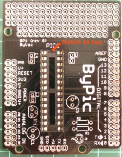
Step 1
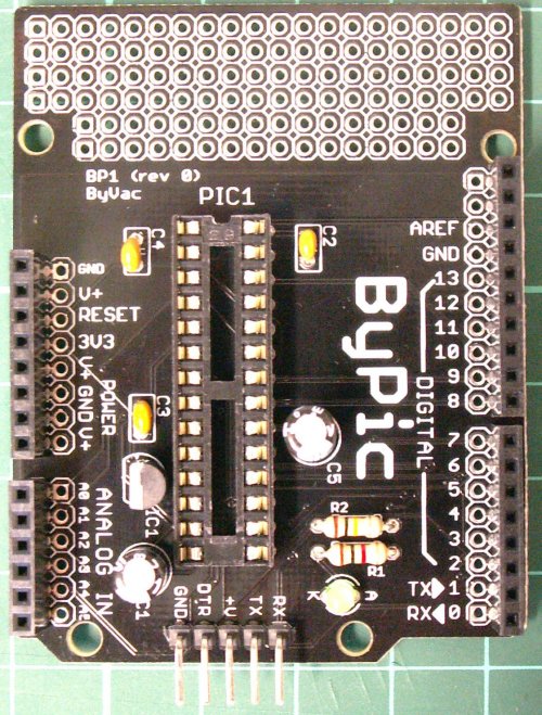
Start by installing the IC socket. The socket has a cut out at the top and this should go towards the prototyping area.
Step 2
Next install the smaller components, C2,3,4 and R1,R2
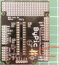
R1 at the bottom has coloured stripes brown, black, red. R2 has stripes brown, black, yellow. This is shown in the picture.
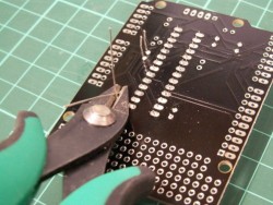
At each stage crop the wire underneath the board to keep it tidy.
Step 3
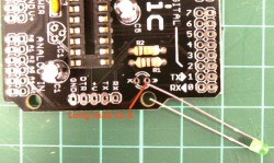
Install the larger capacitors C1 and C5. It is important to get these the correct way round. The long lead goes into the hole marked with a + sign.
Step 4
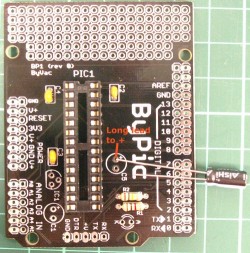
Install the LED. It is important that this goes in the correct way round otherwise it will not illuminate. The long lead goes into the hole marked with an A.
Step 5
Finish the board by mounting the rest of the components, make sure the voltage regulator is the correct way round with the flat side facing outwards.
Step 6
Install the IC, this is the point where static precautions should be taken. The leads of the IC will normally be splayed out and so they need to be pushed back.
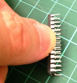
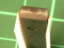
This can be done on a flat surface so that the leads are more or less at right angles as shown in the picture.
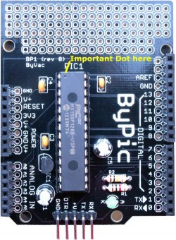
Install the IC the correct way round pin 1, where the dot on the IC is goes to the top as shown. Now everything is complete you will need to power it up and connect to a serial device. Most USB serial devices will have a 5V output which can be used for powering the board.